

 LANGUAGE
 기계는 자동으로 와이어와 케이블을 원으로 감고 감은 후 감쌀 수 있습니다. 일반적으로 포장에는 PP, 종이 테이프, 직조 테이프 및 기타 재료가 사용됩니다. 자동 오류 감지: 장비에 오류가 발생하면 자동으로 오류를 감지하고 경보를 보내 운영자에게 장비의 정상적인 작동 및 유지 관리를 상기시킵니다. 서보모터 케이블 정리 시스템 : 서보 모터 케이블 정리 시스템을 사용하여 아름다운 권선과 이상적인 케이블 정리 효과를 보장합니다. 광범위한 응용 분야: 다양한 전선 및 케이블의 고속 자동 코일링 및 권선 포장에 적합...
더 보기
Shanghai Yessjet Precise Machinery Co., Ltd.;
Jiangsu Yessjet Precise Machinery Co., Ltd.
Jiangsu Yessjet Precise Machinery Co., Ltd.
전선 케이블 권선 기계 제조업체
-
제품 자동 권취기

-
제품 LAN 케이블용 크로스 와인더이 LAN 케이블용 크로스 와인더는 LAN 케이블을 효율적이고 정밀하게 자동으로 감쌀 수 있도록 설계되었습니다. Cat5, Cat5e 및 Cat6을 포함한 주류 LAN 케이블 유형과 완벽하게 호환되며 동축 케이블에도 적용 범위를 확장하여 다양한 배선 및 스토리지 요구 사항을 충족합니다. 이 기계는 케이블을 깔끔한 네트형 코일로 감아 보관이나 운송 중에 엉키거나 손상되지 않도록 질서정연하게 배열합니다. 사용자는 구멍이 있거나 없이 코일을 감을 수 있는 유연한 옵션을 갖고 있으며, 구멍 크기는 직관적인 터치 스크린을 통해...더 보기

코일링 기계는 와이어, 케이블, 호스 또는 스트립과 같은 유연한 재료를 생산, 보관 또는 운송을 위해 깔끔하고 컴팩트한 코일로 감도록 설계된 산업용 장치입니다. 전자, 통신, 제조 등 다양한 분야에 서비스를 제공하는 자동 코일링 기계 및 LAN 케이블 크로스 와인더와 같은 특수 유형을 포괄합니다.
주요 구성 요소에는 안정적인 프레임, 전원 시스템, 장력 제어 및 가이드 메커니즘이 포함되며, 정밀한 매개변수 조정을 위한 PLC 컨트롤러를 갖춘 최신 모델이 있습니다. 자동 버전은 생산 라인, 코일링, 절단, 라벨링 및 포장 처리와 원활하게 통합되어 노동력을 절약합니다. LAN 케이블용 크로스 와인더는 CAT5-CAT8 케이블에 맞게 조정되어 포장 요구 사항에 맞게 구멍 크기를 조정할 수 있는 네트형 코일을 형성합니다.
균일한 장력과 규칙적인 권취를 보장함으로써 기계는 재료 손상을 방지하고 일관된 제품 품질을 보장합니다. 다양한 산업 용도에 맞게 다양한 재료 직경과 코일 무게에 적응하여 수동 노동을 효율적이고 반복 가능한 성능으로 대체합니다.
Shanghai Yessjet Precise Machinery Co., Ltd.
정밀 기계, 지능형 솔루션으로 전 세계 케이블 생산을 지원합니다
Shanghai Yessjet Precise Machinery Co., Ltd. 2002년 대만의 투자로 상하이에 설립되어 전선 및 케이블 기계의 연구 개발에 전념하는 전문 공장으로 시작했습니다. 2017년, 회사 규모 확장을 위해 장쑤 예스젯 정밀 기계 유한회사가 장쑤성 우시시 이싱에 투자했습니다. 전선 케이블 권선 기계 제조업체 및 OEM/ODM 코일 권선 기계 공장 중국.
고성능 생산 시스템(압출 라인, 자동 코일링 기계, 로봇 팔레타이징 솔루션)의 설계 및 제조에 있어 고객이 효율성, 유연성 및 지속 가능한 성장을 달성할 수 있도록 지원합니다. 맞춤형 전선 권선 기계. 모든 자체 제품 라인을 외부 리소스와 통합하여 공정 설계, 장비 선정, 레이아웃 계획, 설치 및 시운전, 인력 교육에 이르는 포괄적인 서비스를 제공함으로써 프로젝트가 첫 번째 시동에 성공할 수 있도록 보장합니다.
더 보기
고성능 생산 시스템(압출 라인, 자동 코일링 기계, 로봇 팔레타이징 솔루션)의 설계 및 제조에 있어 고객이 효율성, 유연성 및 지속 가능한 성장을 달성할 수 있도록 지원합니다. 맞춤형 전선 권선 기계. 모든 자체 제품 라인을 외부 리소스와 통합하여 공정 설계, 장비 선정, 레이아웃 계획, 설치 및 시운전, 인력 교육에 이르는 포괄적인 서비스를 제공함으로써 프로젝트가 첫 번째 시동에 성공할 수 있도록 보장합니다.
YESSJET
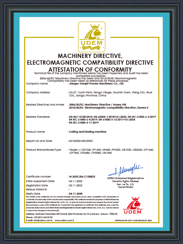
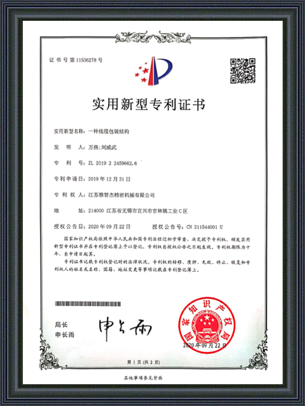
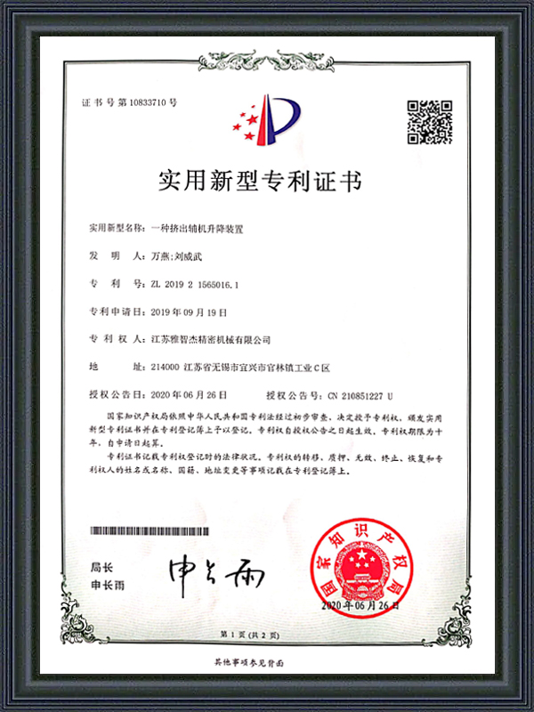
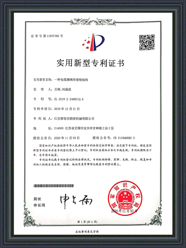
명예 인증
인증서
최신 업데이트
뉴스는 무엇인가요?
-
LAN 케이블용 크로스 와인더: 사용 및 선택 안내네트워크 케이블링에서 크로스 와인더의 역할 이해 A LAN 케이블용 크로스 와인더 이더넷 케이블을 효율적으로 관리, 구성 및 저장하도록 설계된 특수 도구 또는 메커니즘입니다. 전문 네트워킹 환경에서는 케이블 무결성과 구성을 유...
-
자동 와이어 와인딩 머신: 작동 방식 및 올바른 것을 선택하는 방법한 명의 작업자가 수동으로 와이어를 스풀에 감으면 시간당 약 200~400미터를 처리할 수 있습니다. 최고 속도로 작동하는 자동 와이어 와인딩 기계는 코일 장력의 변화도 없고 정렬 불량도 없으며 교대 근무가 끝날 때 피로 관련 오류도 없이 동일한 양을 몇 분 만에 처리합니다....
-
케이블 절연 압출기 및 와이어 및 케이블 압출기: 전체 가이드베어 구리가 들어갑니다. 절연되고 보호된 즉시 배송 가능한 케이블이 나옵니다. 그러한 변화를 가능하게 하는 기계는 케이블 절연 압출기이며, 올바른 기계를 선택하면 공장에서 생산할 모든 미터의 케이블을 성형할 수 있습니다. 이 가이드에서는 이러한 기계의 작동 방식, 핵심 구성 ...
-
자동 케이블 라벨링 기계: 케이블 코일 라벨링 및 라벨 공급 장치 가이드최대 용량으로 가동되는 케이블 생산 라인에서 한 명의 작업자가 담당하는 단일 라벨링 스테이션은 전체 포장 순서에 걸쳐 처리량을 제한하는 병목 현상이 될 수 있습니다. 수동 케이블 코일 라벨링은 느리고 일관되지 않으며 작업자가 피곤하거나 주의가 산만해지면 배치가 비뚤어지고 코...
-
PP PVC PE 케이블 압출기: 케이블 제조업체를 위한 복합 재료 가이드중간에 케이블 압출 라인을 PVC에서 PP로 바꾸면 두 가지 일이 빠르게 잘못될 것입니다. PVC의 비정질 용융 거동에 대해 설정된 배럴 온도는 PP의 결정질 구조에 필요한 수준을 초과하게 되고, 작업자가 반응하기 전에 출력 일관성이 떨어지게 됩니다. 전원 케이블 한 교대, ...
Industry Knowledge
Traversing Mechanism Design: How Wire Distribution Accuracy Affects Coil Quality
The traversing mechanism on a Coiling Machine governs how wire or cable is distributed laterally across the coil width during winding. In most production environments, traverse performance is evaluated by visual inspection of the finished coil face — but this surface check misses the most consequential quality issues, which develop inside the coil body over multiple layers. Uneven pitch distribution — caused by traverse speed mismatch with the winding speed, backlash in the traverse drive leadscrew, or inconsistent pitch programming at diameter transition points — creates localized pressure concentrations inside the coil where layers nest incorrectly. These pressure points distort the insulation geometry of the innermost cable layers and create conditions for abrasion damage during payout, particularly in applications where the cable is pulled from the center of the coil.
The engineering variable that directly controls traverse accuracy is the pitch-to-diameter ratio update rate. As a coil builds in diameter during winding, the linear surface speed at the winding point increases even if the mandrel RPM remains constant. A Coil Winding Machine that does not continuously recalculate and update the traverse pitch to compensate for this diameter growth will produce progressively tighter pitch at the inner layers and progressively wider pitch toward the outer layers — a defect that appears uniform on the coil face but produces a cross-section with non-parallel layer interfaces. Servo-driven traverse systems with real-time diameter compensation, derived either from a layer-count algorithm or from a direct diameter measurement sensor, eliminate this progressive pitch error across the full build height of the coil.
Shanghai Yessjet Precise Machinery Co., Ltd. implements servo-controlled traverse with closed-loop pitch compensation as standard on its Wire Cable Coiling Machine range. The traverse controller receives continuous feedback from the winding mandrel encoder and recalculates the pitch setpoint at every winding revolution, ensuring that the wire lay remains geometrically consistent from the first layer to the last regardless of coil build height or mandrel speed variation during acceleration and deceleration phases.
Dancer Roller Dynamics: Tuning Tension Control for Variable-Speed Winding
The dancer roller assembly on a Wire Coiling Machine performs a function that is more complex than it appears: it simultaneously buffers the speed difference between the upstream line and the coiling mandrel, measures wire tension through its displacement position, and provides the feedback signal that drives the tension control loop. When any one of these three functions is compromised — through incorrect dancer mass, worn pivot bearings, or a poorly tuned PID controller — the tension control system becomes either sluggish or oscillatory, producing coils with layer-to-layer tension variation that is invisible to visual inspection but detectable as conductor elongation variation when the cable is tested for resistance per unit length.
Dancer roller mass is the most frequently underspecified parameter in Cable Coiler installations. A dancer that is too light responds to high-frequency tension disturbances with excessive displacement excursion, saturating the control output and causing the tension loop to lose control during the coil changeover acceleration transient. A dancer that is too heavy has insufficient responsiveness to correct small tension deviations quickly, allowing them to accumulate across multiple coil layers. The correct dancer mass for a given application is determined by the wire's elastic modulus, the target tension setpoint, the maximum expected line speed variation rate, and the dancer arm geometry — a calculation that requires engineering analysis rather than rule-of-thumb estimation.
Dancer Roller Configuration Guide by Wire Type
| Wire/Cable Type | Recommended Dancer Mass | Control Priority | Primary Risk |
| Fine magnet wire (<0.5mm) | Ultra-light (50–150g) | Minimize tension overshoot | Wire break from tension spike |
| Medium building wire (1.5–6mm²) | Medium (0.5–2kg) | Balance response and stability | Layer tension variation, elongation |
| Heavy power cable (>16mm²) | Heavy (3–8kg) | Dampen high inertia transients | Coil collapse from tension loss |
| Flexible multi-core cable | Light-medium (200–800g) | Prevent jacket surface marking | Dancer contact marking on soft jacket |
Beyond mass selection, the PID tuning of the tension control loop requires separate parameter sets for low-speed and high-speed operating ranges. A single PID parameter set that stabilizes tension at 50 m/min will typically be under-damped at 300 m/min, producing visible oscillation in the dancer position that manifests as a rhythmic tension variation at the winding point. Gain-scheduled control — where the PID parameters are automatically adjusted as a function of line speed — is the technically correct solution and is available on modern servo drive platforms without requiring external controller hardware.
Mandrel Expansion Mechanics: Comparing Pneumatic and Servo-Electric Actuation
The expanding mandrel is the defining mechanical component of a modern Wire Cable Coiling Machine — it clamps the coil core during winding, maintains the target inner diameter throughout the winding cycle, and releases the finished coil cleanly for transfer to the downstream packaging station. Mandrel performance directly determines coil inner diameter consistency, transfer cycle time, and the rate of coil release failures that require manual intervention to clear. Despite its centrality to coiling performance, mandrel actuation technology has not been consistently modernized across the industry, and many machines still rely on pneumatic actuators whose limitations become significant at high production speeds.
Pneumatic mandrel actuation operates at a fixed air pressure that determines both the expansion force and the retraction speed. The key limitation is that pneumatic actuation force is not position-controlled — once the actuator reaches end-of-travel, the mandrel arms are held by air pressure alone, and any variation in supply pressure across the shift (common in facilities with shared compressed air systems) translates directly into variation in mandrel grip force. When grip force drops below the threshold needed to resist the winding tension at the outer coil layers, the mandrel slips rotationally, producing a layer displacement defect in the upper coil body that is difficult to detect until the coil is transferred and the defect becomes visible on the coil face.
Servo-electric mandrel actuation resolves this limitation by replacing the pneumatic cylinder with a servo motor and ballscrew or toggle mechanism that positions the mandrel arms to a precisely defined diameter and holds that position through motor torque rather than air pressure. The servo system provides real-time position feedback that confirms the mandrel is at the commanded diameter before the winding cycle begins, and maintains the commanded position throughout the winding cycle regardless of the reaction force from winding tension. Coil inner diameter repeatability on servo-actuated mandrels is typically ±0.5mm or better across a full production shift, compared to ±2–4mm on pneumatic systems under variable supply pressure conditions.
Cut-and-Transfer Sequence Optimization on High-Speed Cable Coilers
The cut-and-transfer sequence on a Cable Coiler — the coordinated series of events that ends one coil, cuts the cable, secures the tail, and positions the new coil core for winding — is the most time-critical phase of the entire coiling cycle. At line speeds of 300 m/min or above, the upstream cable production during a 3-second transfer sequence represents 15 meters of cable that must be accommodated in the accumulator buffer without causing a tension spike or a slack loop. Buffer capacity, cut timing, and transfer arm kinematics must be engineered as an integrated system rather than specified independently, because an underspecified buffer or a slow transfer sequence creates a constraint that limits the entire line's effective output speed regardless of the winding speed capability of the Cable Coiler itself.
The cut event itself requires precise synchronization between the cutter actuation signal and the cable position at the cutter blade. On rotary flying cutters — which cut the cable while both the cable and the cutter blade are in motion — the blade timing must account for the cable transport delay between the cutter position and the winding point. If the blade fires too early, the tail length on the finished coil is shorter than specified; if it fires too late, the lead length on the new coil extends past the first winding layer, creating a loose external tail that interferes with the strapping operation. The acceptable timing window for a clean cut at 300 m/min is typically less than 20 milliseconds, requiring a PLC with deterministic scan times rather than a general-purpose controller with variable cycle time.
- Buffer accumulator sizing: The minimum accumulator capacity must equal the cable output during the full transfer sequence time at maximum line speed — undersized accumulators force the upstream line to decelerate during every coil change, creating a cyclic speed disturbance that affects extrusion wall thickness consistency
- Tail securing method: Hot-air tail tucking is more reliable than mechanical tail clips for soft-jacketed cables at high speed because it does not require the tail to be presented at a precise position — the hot air stream deflects the tail regardless of its exact angle at the moment of cut
- Core pre-positioning: The new coil core should be loaded and confirmed in the standby mandrel position before the cut event, not after — any delay in core positioning after the cut extends the effective transfer time and increases the accumulator demand
- Transfer arm velocity profiling: The transfer arm should follow an S-curve velocity profile rather than a trapezoidal profile to minimize the jerk at the start and end of the transfer motion — high jerk values during coil transfer cause the finished coil to shift on the transfer arm, producing misaligned placement at the downstream strapping station
Preventive Maintenance Intervals for Wire Coiling Machine Mechanical Systems
Wire Coiling Machine mechanical systems operate under continuous cyclic loading that creates wear patterns distinct from those seen in most other types of industrial machinery. The mandrel expands and contracts on every coil cycle — potentially 300 to 500 times per shift on a high-speed building wire line — subjecting the mandrel pivot bearings and actuator mechanism to a cumulative cycle count that reaches millions of cycles within the first year of operation. Standard machinery maintenance intervals based on operating hours significantly underestimate the mechanical wear rate for these components, because the relevant degradation driver is cycle count rather than run time. A Wire Coiling Machine running at 400 m/min winding 50m coils accumulates 480 mandrel cycles per hour — eight times the cycle rate of a machine running the same hours but winding 400m coils.
Establishing maintenance intervals based on coil cycle count rather than operating hours requires the machine control system to log cumulative cycle counts for each wear-critical component and present maintenance alerts at the appropriate thresholds. This is a standard feature in modern Coil Winding Machine control platforms but is absent in older relay-logic or basic PLC-controlled machines, requiring operators to track cycle counts manually — a practice that is rarely maintained consistently in production environments. Where cycle-count tracking is not available in the control system, a conservative approach is to set time-based maintenance intervals at one-third of the supplier-recommended hours for high-cycle-count mechanical components.
Recommended Maintenance Intervals by Component and Trigger Basis
| Component | Maintenance Action | Cycle-Based Interval | Failure Mode if Neglected |
| Mandrel pivot bearings | Lubrication / replacement | Every 500,000 cycles | ID variation, mandrel arm seizure |
| Traverse leadscrew / belt | Backlash check / tension | Every 2,000 hours | Pitch error, layer misalignment |
| Dancer roller bearings | Friction check / replacement | Every 1,500 hours | Tension control instability |
| Cutter blade | Sharpness inspection / replacement | Every 200,000 cuts | Ragged cut, jacket burr, tail length error |
| Transfer arm guide rails | Wear measurement / lubrication | Every 3,000 hours | Coil misplacement, strapping station jam |
Founded in 2002 in Shanghai with investment from Taiwan, and expanded through Jiangsu Yessjet Precise Machinery Co., Ltd. in Yixing in 2017, Shanghai Yessjet Precise Machinery Co., Ltd. provides customers with a documented maintenance schedule specific to each Wire Coiling Machine configuration — not a generic equipment manual, but a maintenance plan calibrated to the actual coil cycle rate, product mix, and operating environment of the customer's facility. This schedule is delivered as part of the commissioning package and includes cycle-count thresholds for all wear-critical components, a recommended spare parts inventory sized for six months of planned maintenance, and a diagnostic checklist that operators can use to identify early-stage wear indicators before they develop into unplanned downtime events.
빠른 링크


저작권 © Shanghai Yessjet Precise Machinery Co., Ltd. 모든 권리 보유. 맞춤형 전선 권선 기계 공장
